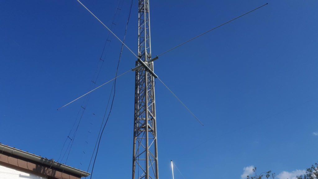
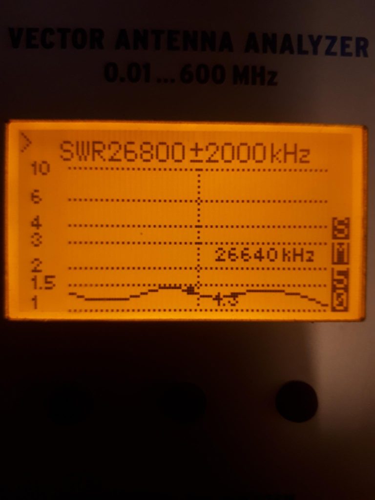
Vertical antennas like ground planes are omnidirectional and known to pick up more noise than horizontal dipoles. Horizontal dipoles are a bit quieter, but not omnidirectional. According to an article ‚ The Importance of Circular Polarisation for Diversity Reception and MIMO in NVIS Propagation‘ issued by University of Twente, Netherlands, reflected signals coming down from the ionosphere are never vertical or horizontal, they split up into two waves with circular polarisation of opposite sense. One right hand circular polarized RHCP, the other one being a delayed left hand circular polarized LHCP signal AND with more fading. This applies to signals received in the northern hemisphere. If you are in the southern hemisphere, the opposite applies, RHCP is delayed and fades more. So why not build an antenna that is omnidirectional, neither vertical or horizontal polarized, but circular. I found a very interesting antenna in german ham magazine Funkamateur issued in April 22. It is a circular polarized cross dipole with broad match from 12m -10m . Built this antenna and am very pleased with it. The advantage over a vertical or horizontal antenna is less fading. I got an unscientific confirmation in a 10m qso with a station in EA, a german op, using a vertical. His signal was readable all the time with only little qsb, while he confirmed my signal rapidly fading from 59 to almost unreadable and back. More qso’s to be made to proof this, of course.
Losses on vertical signals from stations in the neighbourhood coming in over ground wave are smaller than with a horizontal dipole antenna and because it is omnidirectional, you don’t have the losses from wrong direction related to a horizontal bidirectional dipole.
You need: 2.72m rods per half dipole , wires connecting the coax to the aluminum rod included. If the wire connecting the coax to the rod is 10cm long, rods must be 2.62m . Or in other words: Just make sure one half of the dipole plus the jumper wire to the coax is 2.72m in total.
1.85m 75Ohm cable (if velocity factor is 0.66)
50 Ohm feedline to the shack.
A W1JR common mode choke.
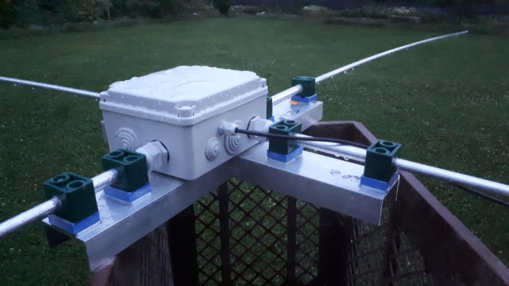
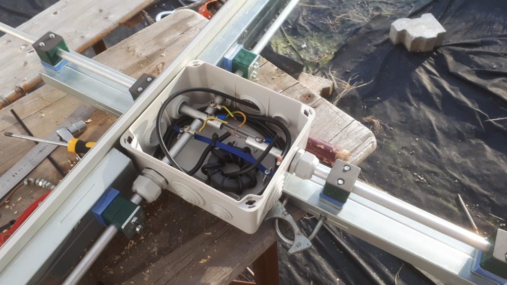
Connections are: At the antenna end of the 50 Ohm feedline coming from the shack, attach a W1JR balun.
Connect the balun to dipole #1. Now connect one end of the delay line to dipole #1 and the other end to dipole #2 . That’s it. The sense of rotation is discussed below.
Single Band circular polarized Antenna
If you don’t need the antenna cover a wide frequency range but rather want to have a single band antenna, here’s some cool thing:
Make a dipole, cut it to length for a good match on the band of interest, then make a second dipole with exactly the same dimensions. Common mode chokes for both is a good idea. Now mount them onto your antenna tower.
Attach 50 Ohm coax lines of exactly equal length to both of them. At the shack end, you will find 25 Ohms of impedance if you connect both lines same time to your analyzer. Now connect both lines to a 1/4 wave transformer made of 2 parallel 75 Ohm cables. The principle is shown on DK7ZB’s excellent antenna pages: Cross yagi Fig.4 & Fig.5 and the 2 pictures showing how to connect.
You should now measure 50 Ohms at the other end.
If you made your dipoles for 10m, the formula for the transformer is ((300/28,5)/4)*0,66=1.73m if you use RG59 (fiftyNINE , VF 0.66) . TV-cable has a VF of 0.8 .
Now you have linear polarization. If you want circular, you must add a 50 Ohm 1/4 wave delay line to one of the dipoles. The formula is the same as for the transformer, so the delay line is a 1.73m long RG58 (fiftyEIGHT).
Here is the cool thing: You can swap feedlines in the shack. Your choices are
east/west horizontal bidirectional: coax from north/south dipole directly to radio
north/south horizontal bidirectional: coax from east/west dipole directly to radio
horizontal linear omnidirectional: both coaxes via 75 Ohm transformer to radio
RHCP/LHCP: Standing under your antenna looking up, you see dipole A pointing 12 and 6 o’clock, dipole B pointing 3 and 9 o’clock. Connect center conductor to dipole A, 12 o’clock and the braid to dipole A , 6 o’clock. Connect the delay line to the other dipole. If you want RHCP, center conductor goes to dipole B, 9 o’clock and braid goes to dipole B, 3 o’clock. If you want LHCP, swap center conductor and braid attached to dipole B. Cool!